



Automatic Transfer Switching Equipment
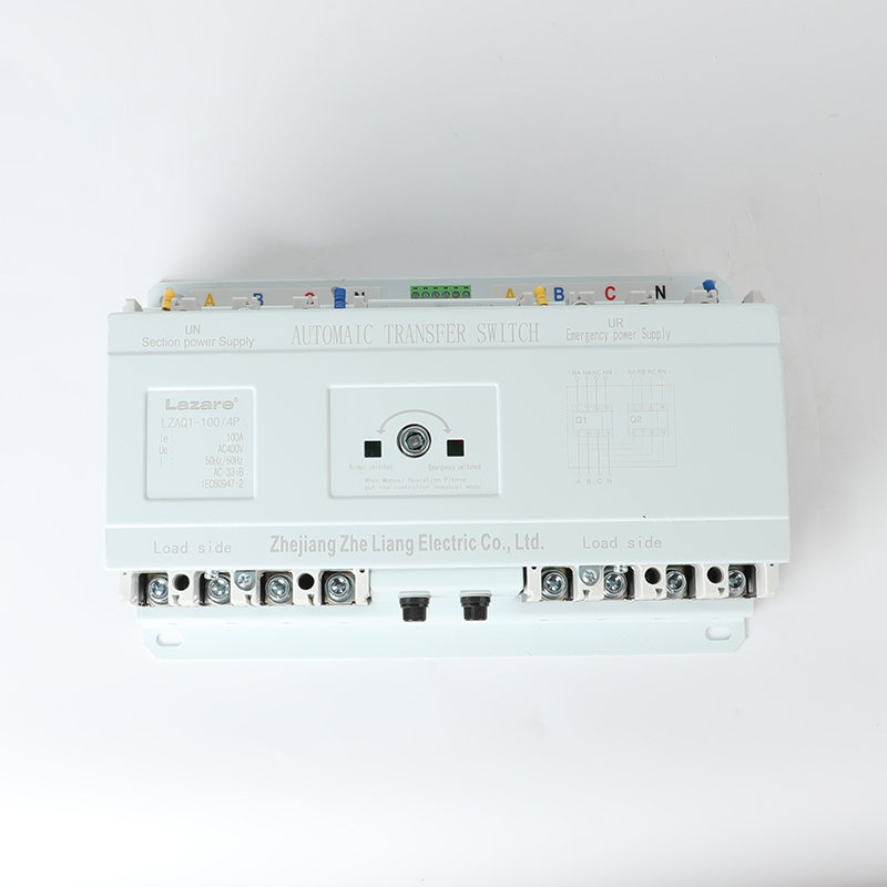
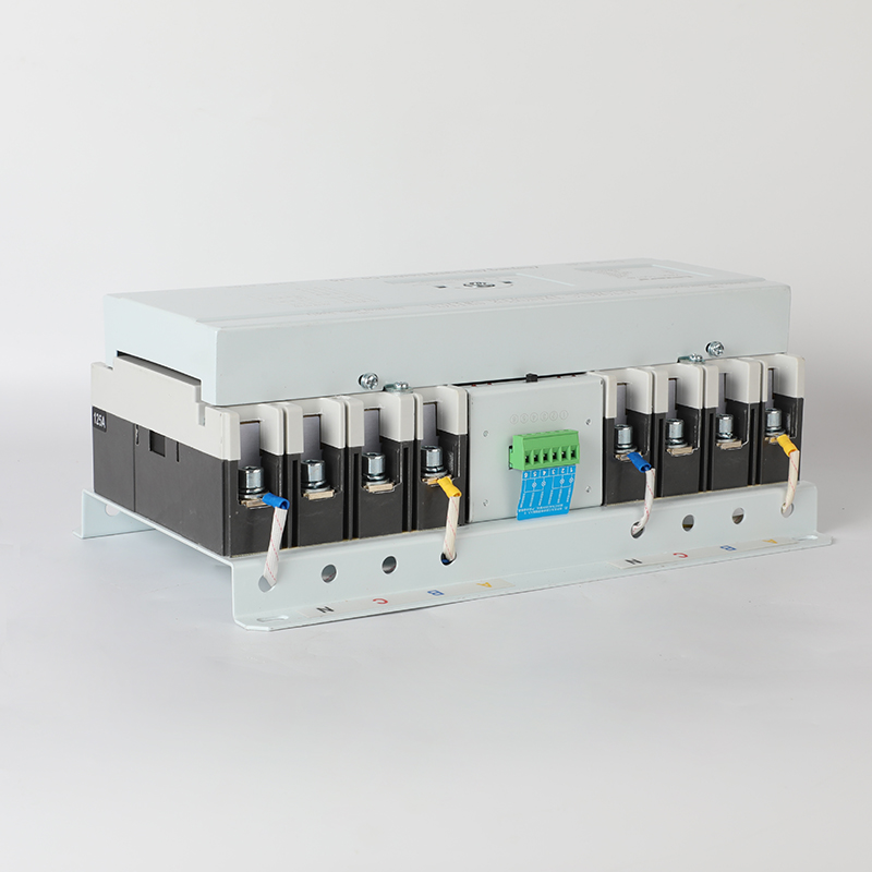
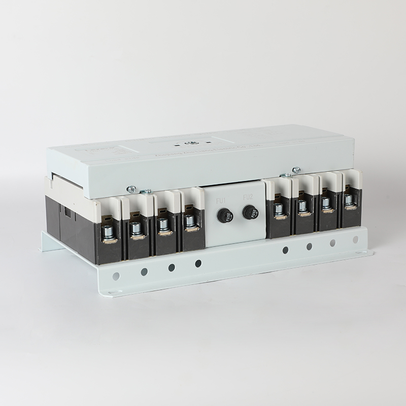
LZAQ1 series intelligent dual power automatic transfer switch
Applicable Scope
LZAQ1 series intelligent dual power automatic transfer switch (hereinafter referred to as transfer switch) is composed of molded case circuit breaker or load switch as actuator, interlocking transfer mechanism and automatic controller with single chip as core. It is a dual power automatic transfer switch with perfect performance, safety and reliability, high degree of automation and wide application range. It has the characteristics of simple and reliable structure, beautiful appearance, complete specifications and convenient operation and maintenance.
This product is suitable for AC 50/60Hz, 690V and below, rated current from 6A to 1250A and below, in a power supply system composed of two power supplies (normal power supply N and backup power supply or generator power supply R). When one power supply fails (power outage, phase failure, undervoltage, overvoltage), the power supply is automatically switched to ensure the reliability and safety of power supply. It is widely used in high-rise buildings, residential areas, hospitals, airports, docks, fire protection, metallurgy, chemical industry and other important places where power outages are not allowed to achieve unattended continuous power supply. The product complies with GB/T14048.11 standard. Electrical grade CB grade (the main contact can connect and disconnect short-circuit current and is equipped with overcurrent release).
Working Conditions
1. The upper limit of the ambient air temperature shall not exceed +40℃, the lower limit shall not be lower than -5℃, and the average value of 24h shall not exceed +35℃;
2. The relative humidity of the atmosphere shall not exceed 50% when the ambient air temperature is +40℃, and higher relative humidity can be achieved at lower temperatures. The average maximum relative humidity of the wet month is 90% and the average minimum temperature of the month is +25℃, and condensation on the product surface due to temperature changes shall be taken into account;
3. The installation location altitude shall not exceed 2000m;
4. The installation category is IV.
5. This product should be installed in a place without severe vibration and impact, and where the electrical components are not subject to unnecessary corrosion.
Main performance and parameters
1. The automatic transfer switch can complete the automatic switching of power in the dual power supply system of single-phase two-wire, three-phase three-wire and three-phase four-wire; the intelligent controller decides whether to switch from one power supply to another according to the voltage state of the working power supply and the working mode set by the user.
2. The transfer switch has three stable working positions: normal power closed, standby power open position (normally closed); normal power open, standby power closed position (standby closed); normal power
The power supply and backup power supply are both divided into gate positions (double division).
3. The transfer switch has three operation modes: automatic operation by the controller, manual operation by the controller, and manual operation by the operating handle.
4. The transfer switch is driven by a noiseless motor, and the switching is reliable and smooth, without impact on the power grid. It is also equipped with electromechanical interlocking protection to ensure that only one power supply can be supplied at the same time, ensuring power supply safety. The actuator has a high breaking capacity and can automatically switch with load. In an emergency, the handle can be used for manual switching.
5. The main technical performance of the automatic transfer switch is shown in the table below.
|
Project |
LZAQ1 - 100 ~ 225 |
LZAQ1 - 400 |
LZAQ 1 - 630 ~ 1250 |
|
|
Rated working voltage(V) |
Ue |
400 |
400 |
400 |
|
Rated frequency(Hz) |
|
50 / 60 |
50 / 60 |
50 / 6 |
|
Rated insulation voltage(V) |
Ui |
690 |
690 |
690 |
|
Rated impulse withstand voltage(kV) |
Uimp |
6 |
6 |
6 |
|
Rated short-circuit making capacity (kA) |
Icm |
35 |
50 |
50 |
|
Rated short-circuit breaking capacity (kA) |
Icn |
17 |
25 |
25 |
|
Use Category |
|
AC- 33 iB |
AC- 33 iB |
AC- 3 iB |
|
Contact switching time (s) |
|
≤2 |
≤3 |
≤3 |
|
Electrical level |
|
CB |
CB |
CB |
|
Undervoltage switching setting range (V) |
|
155~205 |
155~205 |
155~205 |
|
Overvoltage switching setting range (V) |
|
230~280 + OFF |
230~280 + OFF |
230~280 + OFF |
|
Conversion and return delay(s) |
|
0~22 s Adjustable |
0~22 s Adjustable |
0~22 s Adjustable |
|
Electrical life (times) |
|
1000 |
1000 |
500 |
|
Mechanical life (times) |
|
5000 |
3000 |
2500 |
|
Total service life times (times) |
|
6000 |
4000 |
3000 |
|
Controller operating voltage |
|
Phase voltage (need N pole) AC220V±15%, power consumption ≤5W |
||
Dual power automatic controller
The dual power controller has three structural forms according to user needs: intelligent one-piece type (type B), intelligent split type (type D), and economical built-in type (type C). The main differences between the three controllers are shown in the following table:
| Controller Type | Economical type (Type C) | Intelligent one-piece type (Type B) | Intelligent split type (D type) |
| Distinction Project | |||
| Installation location | Inside the switch | Switch base, right side | On the cabinet panel, connected to the switch with a cable |
| Switch working position | Two working positions | Three working positions (normally closed, ready to close, double open) | |
| How to operate | Automatic/manual handle operation | Automatic/manual button operation/manual handle operation | |
| Fire linkage function | Fire trip function | Fire double function | |
| Generator control | none | Optional automatic start and stop control of generator | |
| Conversion method | Self-transfer and self-recovery method | Self-investment and self-recovery, self-investment and non-self-recovery | |
| Conversion delay function | Fixed 0.2 seconds | Adjustable 0-22 s | |
| Return delay function | Fixed 0.2 seconds | Adjustable 0-22 s | |
| Voltage monitoring and display | A phase power failure monitoring, no display | Common and standby six-phase voltage monitoring (undervoltage, overvoltage, phase failure, power failure), LCD display | |
| project | illustrate |
| Automatic control function | Automatic transfer and automatic recovery function① |
| Automatic transfer without automatic recovery function② | |
| Monitor common power supply and automatically switch (three-phase failure, overvoltage, undervoltage detection) | |
| Monitor backup power and automatically switch (three-phase failure, overvoltage, undervoltage detection) | |
| Generator control (automatically start and stop the generator)③ | |
| Fire signal input, automatically switches to "double break" state④, optional feedback signal output. | |
| Display functions | Switch working status display: manual, automatic, automatic switching and automatic recovery, automatic switching without automatic recovery, etc. |
| Power failure phase indication: When a phase fails, the phase number will not be displayed and the alarm character will flash. | |
| Real-time monitoring of each phase voltage and frequency: and cyclic display of the current power supply three-phase voltage | |
| Setting parameter indication: intelligent and user-friendly, on-site adjustment of working mode, voltage threshold, delay time, etc. | |
| “Alarm” indication: The controller can display an alarm when a fault occurs. | |
| Working position indication function | Normally closed: the normal power supply is put into operation and the backup power supply is disconnected |
| “Backup”: The backup power supply is put into operation and the normal power supply is disconnected; | |
| “Double disconnection”: both normal power supply and backup power supply are disconnected. | |
| Manual button operation | Forced to work in three stable positions: normal power supply, backup power supply, and double power supply |
| Query function | Press the "Query" button on the controller to cyclically display: NC phase frequency, RC phase frequency, conversion delay (C), return delay (b), current NA, NB, NC, RA, RB, RC phase voltages. |
【Note】
① The automatic controller with self-transfer and self-recovery (R) function automatically switches the two power supplies (normal power supply N and backup power supply R). In normal state, the normal power supply is used for power supply. When the normal power supply is abnormal and the backup power supply is normal, it automatically switches to the backup power supply after the set transfer delay C (adjustable from 0 to 22s). When the normal power supply returns to normal, it can switch to the normal power supply after the set return delay b (adjustable from 0 to 22s).
② The automatic controller with the function of automatic transfer but not automatic recovery (S) automatically switches the two power supplies (normal power supply N and backup power supply R). In normal state, the normal power supply is used for power supply. When the normal power supply is abnormal and the backup power supply is normal, it automatically switches to the backup power supply after the set conversion delay C (adjustable from 0 to 22s). When the normal power supply returns to normal, it cannot automatically switch to the normal power supply. It is not until the backup power supply is abnormal that it automatically switches to the normal power supply after the set return delay b (adjustable from 0 to 22s).
③ Generator self-starting function: When the power is normal, the relay is closed and the generating contacts are disconnected; when the power is abnormal, after the conversion delay (such as when the power is off, there is no delay), the generating signal is issued.
The generating contacts are closed, and when the generating voltage reaches normal, it automatically switches to the generator power supply; when the common power supply returns to normal, it automatically returns to the common power supply, the generating contacts are disconnected with a delay, and the generator stops generating electricity.
④ If there is a fire signal, the conversion switch will perform a double-break operation and automatically return to the "double-break" state. At this time, you need to press the manual automatic key to reset and return to normal working state.
Installation Dimensions
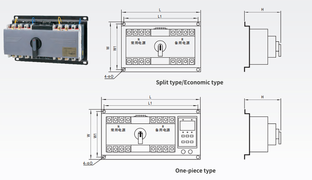
|
Dimensions (mm) Model |
One-piece appearance and installation dimensions |
Split/Economical Appearance and Installation Dimensions |
||||||||||
|
L |
L1 |
W |
W1 |
H |
D |
L |
L1 |
W |
W1 |
H |
D |
|
|
LZAQ1-63/3P |
440 |
410 |
220 |
200 |
150 |
9 |
360 |
330 |
220 |
200 |
150 |
9 |
|
LZAQ1-63/4P |
440 |
410 |
220 |
200 |
165 |
9 |
360 |
330 |
220 |
200 |
165 |
9 |
|
LZAQ1-100/2P |
440 |
410 |
220 |
200 |
150 |
9 |
360 |
330 |
220 |
200 |
150 |
9 |
|
LZAQ1-100/3P |
440 |
410 |
220 |
200 |
148 |
9 |
360 |
330 |
220 |
200 |
148 |
9 |
|
LZAQ1-100/4P |
440 |
410 |
220 |
200 |
165 |
9 |
360 |
330 |
220 |
200 |
165 |
9 |
|
LZAQ1-225/2P |
460 |
430 |
240 |
220 |
165 |
9 |
380 |
350 |
240 |
220 |
165 |
9 |
|
LZAQ1-225/3P |
460 |
430 |
240 |
220 |
165 |
9 |
380 |
350 |
240 |
220 |
165 |
9 |
|
LZAQ1-225/4P |
460 |
430 |
240 |
220 |
185 |
9 |
380 |
350 |
240 |
220 |
185 |
9 |
|
LZAQ1-400/3P |
580 |
600 |
310 |
280 |
220 |
11 |
520 |
490 |
310 |
280 |
220 |
11 |
|
LZAQ1-400/4P |
580 |
600 |
310 |
280 |
220 |
11 |
520 |
490 |
310 |
280 |
220 |
11 |
|
LZAQ1-630/3P |
690 |
710 |
350 |
320 |
225 |
11 |
630 |
600 |
350 |
320 |
225 |
11 |
|
LZAQ1-630/4P |
690 |
710 |
350 |
320 |
225 |
11 |
630 |
600 |
350 |
320 |
225 |
11 |
|
LZAQ1-800/3P |
710 |
655 |
340 |
315 |
190 |
11 |
610 |
555 |
340 |
320 |
190 |
11 |
|
LZAQ1-800/4P |
780 |
730 |
340 |
315 |
190 |
11 |
660 |
625 |
340 |
315 |
190 |
11 |
|
LZAQ1-1250/3P |
730 |
675 |
380 |
360 |
280 |
11 |
660 |
630 |
380 |
360 |
280 |
11 |
|
LZAQ1-1250/4P |
800 |
745 |
380 |
360 |
280 |
11 |
695 |
640 |
380 |
360 |
280 |
11 |